
À PROPOS DE NOUS
La société Yantai Yunde Intelligent Technology Co., Ltd., forte de seulement 30 ans d'expérience en production, a servi plus de 300 clients nationaux et étrangers et a produit plus de 2 000 machines.
DEMANDEZ UN DEVIS GRATUIT
-
Maison

-
Blog
-
Blogs de l'industrie
- How to Fix Common Steel Bar Straightening Problems

How to Fix Common Steel Bar Straightening Problems
-
auteur
- 3,septembre
 auteur
Steel bars can look straight yet fail inspection because of bow, diameter, or surface condition changes from end to end. A stable result comes from connecting the defect with roll pressure, guide alignment, entry material, and measurement. This guide keeps the focus on bar straightening so teams correct causes instead of repeatedly turning adjustment screws.
Why a straight bar can still fail inspection
A bar may look straight on a rack while its measured straightness varies along the length. Springback, end diameter change, or a contact mark can show that correction load was uneven. Inspect several positions and rotate the bar instead of relying on one sight line.
Entry diameter, length, alloy strength, and initial-bow direction set the correction window. When stock changes but the setting does not, a stable bar straightening process can produce alternating bends or end distortion.
Symptom patterns on finished bars
The defect pattern usually points to the first variable worth checking. Record the same locations after each change.
*One-sided bow: check guide centering and roll-gap symmetry.
*Residual curve: check springback compensation and material change.
*Waves or marks: check local reduction, roll cleanliness, and load stability.
*End shrinkage: check pressure release and end support.
A quick diagnosis before changing roll settings
Change one variable at a time and keep a reference bar. Measure the same positions before and after, then record feed speed and load. Use the table as a first diagnostic sequence, followed by a controlled trial.
| Observed Straightening Issue | Likely Cause | Recommended Inspection or Adjustment |
| One-sided bow | Guide or roll alignment | Measure gap and guide center at entry, middle, and exit |
| Wavy surface | Too much local reduction or unstable load | Inspect roll contact, load trend, and roll cleanliness |
| End diameter change | Pressure release or end support | Compare the first and last 200 mm with the middle section |
| Curve returns after release | Insufficient compensation for springback | Repeat the pass at a controlled load and speed |

Roll pressure and alignment control the correction
A two-row roller arrangement corrects the bar through repeated direction changes. Concave and convex rolls create linear contact along the length, distributing correction instead of concentrating it at one point. The resulting precision straightening roll system needs enough load to overcome the bend while keeping support and roll gap stable.
Constant pressure helps when material strength varies. A separate hydraulic system can hold and release load in sequence, while a rigid frame keeps the roll-gap position accurate and protects the machine during high-load correction.
Set correction around material behavior
High-strength bars often need gradual load increase because elastic recovery is greater. Start from the measured bend and stop when the result is stable; excess pressure can create end reduction, marks, or roll wear.
*Confirm diameter, length, and material grade.
*Center guides before fine roll adjustment.
*Verify straightness, diameter, and surface roughness together.
BS-series ranges that frame the adjustment decision
Model selection is part of defect prevention. A machine near the edge of its range leaves less room for stable support, so the BS model should cover the actual bar rather than only the nominal order size. The ranges below frame a round bar straightening machine trial.
| Modèle | Plage de diamètres (mm) | Longueur (m) | Speed (m/min) | Tolérance de diamètre | Rugosité de surface (μm) | Rectitude (mm/m) | Main Motor Power(kW) | Structure |
| BS20 | Φ6–20 | ≥2 | 10–40 | ≤IT8 | Ra≤0,8 | 0.10 | 7.5×2 | Cadre |
| BS40 | Φ10–40 | ≥2 | 10–35 | ≤IT8 | Ra≤0,8 | 0.15 | 22×2 | Cadre |
| BS60 | Φ15–60 | ≥2 | 10–30 | ≤IT8 | Ra≤0,8 | 0.20 | 30×2 | Cadre |
| BS80 | Φ20–80 | ≥2 | 10–24 | ≤IT8 | Ra≤0,8 | 0.25 | 37×2 | Cadre |
| BS100 | Φ25–100 | ≥3 | 10–24 | ≤IT8 | Ra≤0,8 | 0.30 | 45×2 | Cadre |
| BS130 | Φ35–130 | ≥3 | 10–20 | ≤IT8 | Ra≤0,8 | 0.35 | 75×2 | Cadre |
| BS160 | Φ40–160 | ≥3 | 10–20 | ≤IT8 | Ra≤0,8 | 0.40 | 90×2 | Cadre |
Process checks that prevent repeat defects
Yunde BS-series supports repeatable bar correction. A machine à redresser les barres d'acier page can help a technical team compare the BS range with its own diameter, length, speed, and straightness targets.
Production data closes the loop
A useful production record contains the model, material, diameter, length, feed speed, load or pressure setting, measured straightness, and the operator defect description. Over time, these records show whether a problem follows one material batch, one size, one guide position, or one speed range. That evidence is more valuable than a general claim that the line is running fast.
The same discipline supports a metal straightening production line review: define the target, measurement point, and handling checks so the bar is not re-bent.
When to stop adjusting and inspect the incoming bar
Repeated adjustment is not always the answer. If the defect returns after guides, load, and speed are checked, inspect incoming diameter spread, initial bow, and surface condition. A straightening unit cannot remove every upstream variation without added risk.
Escalate when the defect is concentrated at one end, appears only on one batch, or changes after handling. A controlled sample and clear measurement points show whether the straightening unit, material, or handling path needs attention.

A repeatable correction routine
A repeatable routine verifies material and model range, checks guides, sets pressure gradually, and measures several positions. The BS20–BS160 range covers Φ6–Φ160 mm bars with stated straightness values from 0.10 to 0.40 mm/m. Yunde can discuss the target through its technical consultation page.
FAQ
What causes a bar to leave a straightening machine with a one-sided bow?
A one-sided bow points to guide offset, unequal roll-gap alignment, or an off-center entry. Check the guide and gap before increasing load, then rotate a sample to separate runout from alignment.
How do I know whether roll pressure is too high?
Pressure is likely too high when end reduction, marks, rising load, or waviness appears without better straightness. Reduce the change and compare ends with the center.
What is the role of feed speed in bar straightening?
Feed speed changes contact time. A faster setting can reduce stability on strong or badly bent bars, so compare speed and load together.
Can a straightening machine handle high-strength bars?
Yes, when the model covers the bar and load, guides, speed, and verification are controlled. A straightening unit handling high-strength material needs gradual adjustment and closer springback monitoring.
Article récent

Produits associés
Produits les plus vendus
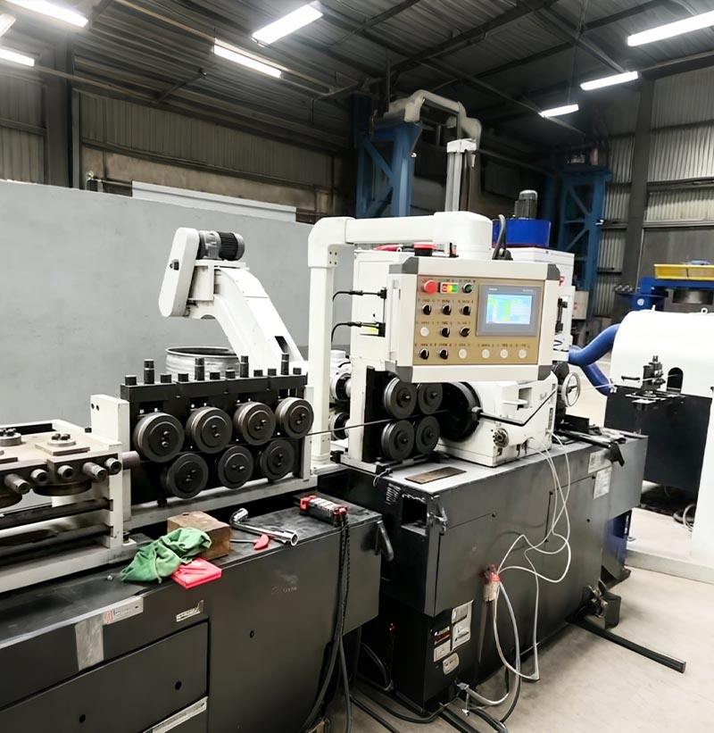
Ligne de lissage Coil To Bar
Le fil machine en acier inoxydable est déroulé et pré-redressé, puis élagué à l'aide d'un tour sans centre et coupé à une longueur précise. Après un dernier passage de redressage de précision dans une redresseuse à deux rouleaux, on obtient une barre droite en acier inoxydable de haute précision.
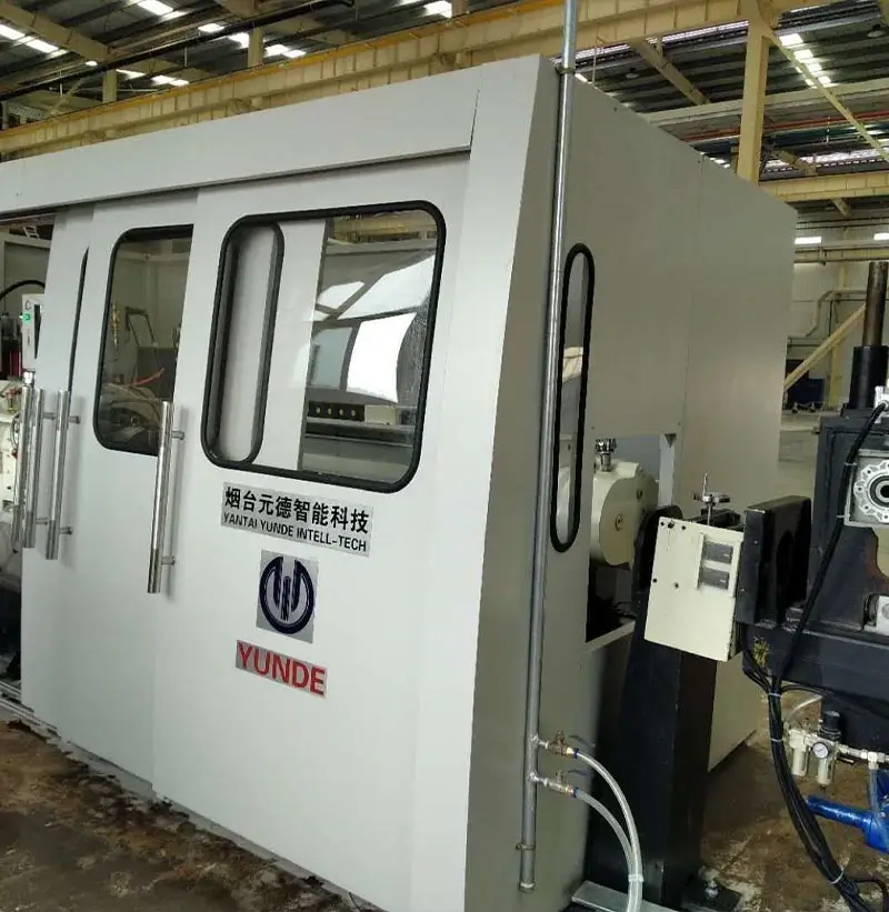
Machine à peler (tour sans centre)
L'unité de machine à peler (tour sans centre) est un produit développé indépendamment après avoir comparé et contrasté les avantages de produits étrangers similaires et les avoir combinés avec les caractéristiques de production des entreprises nationales, ce qui a abouti à une conception simplifiée et optimisée.
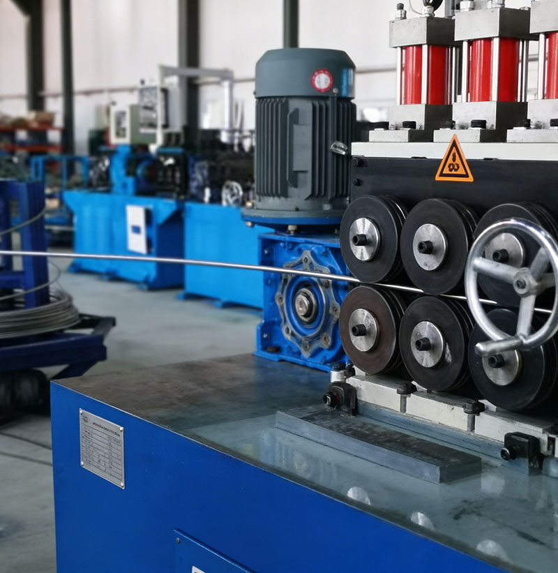
Ligne de production bobine à bobine
La ligne de production de bobine à bobine est composée d'une série de machines comprenant une dérouleuse et redresseuse, une éplucheuse, un mécanisme de serrage, un dispositif de pré-cintrage, une enrouleuse, etc. Grâce à ces machines, la barre de bobine noire est transformée en barre de bobine brillante de haute qualité.
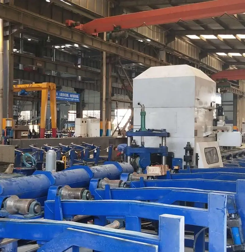
Machine à lisser série BS
Une redresseuse est un appareil servant à redresser les profilés, barres, tubes et fils métalliques. Elle utilise des rouleaux redresseurs pour comprimer le matériau et ainsi le redresser. Généralement, elle comporte deux rangées de rouleaux, dont le nombre peut varier. Il existe également des redresseuses à deux rouleaux, qui exploitent la variation d'angle de deux rouleaux (de forme concave ou hyperbolique) pour redresser des matériaux de diamètres différents.
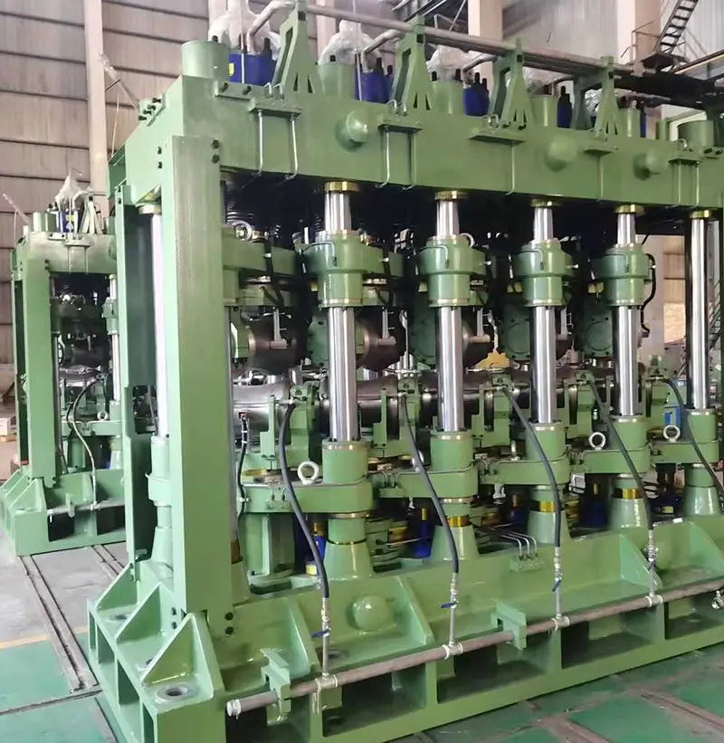
Machine à redresser les tubes en acier à rouleaux multiples
Il s'agit d'un dispositif mécanique servant à redresser la courbure et l'ovalisation des tubes en acier. Il est utilisé pour redresser les tubes en acier fortement allié, résistant à la corrosion, réfractaire, en acier et alliages réfractaires, en fer-nickel, en nickel et en alliages de titane, afin de réduire les défauts de rectitude longitudinale et de circularité transversale.
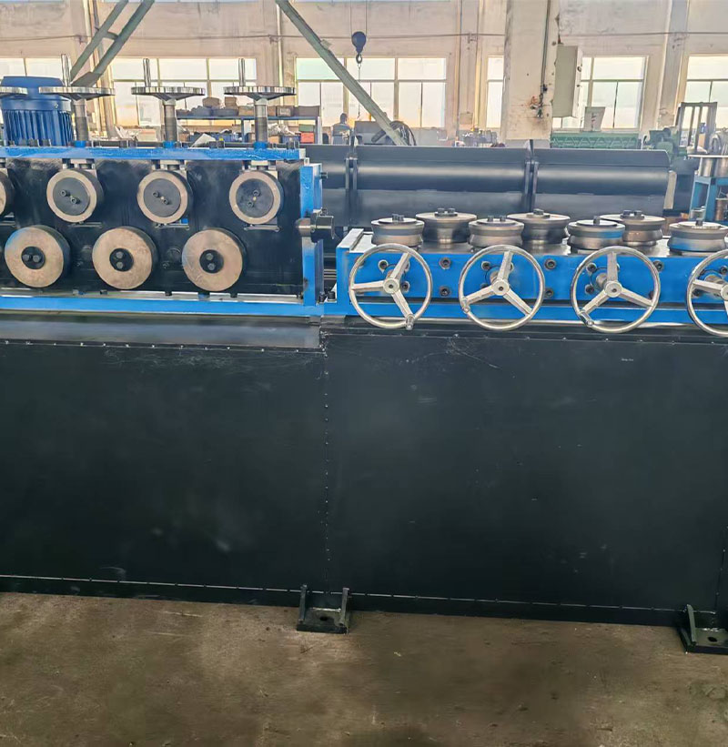
machine à redresser horizontale et verticale
Relâchez le volant de la redresseuse horizontale et verticale à plusieurs rouleaux pour permettre à la bobine de fil de passer entre les rouleaux de redressage. Serrez le volant jusqu'à la position déterminée empiriquement, mettez en marche le dispositif d'alimentation et effectuez plusieurs essais de redressage. Alimentez ensuite la bobine de fil avec les rouleaux de redressage verticaux, en suivant la même procédure que pour le redressage horizontal. Enfin, alimentez la machine à dénuder avec la bobine de fil.