
회사 소개
옌타이 윈더 지능형 기술 유한회사는 30년의 생산 경력으로 300곳이 넘는 국내외 고객에게 서비스를 제공했으며 2,000대 이상의 기계를 생산했습니다.
무료 견적 받아보세요

How to Select Cutting Tools for Steel Bar Peeling Machines?
-
 작가
작가 - 23,9월
A cutting insert that lasts well on one steel batch can chip early on the next. For a steel bar peeling machine, the useful choice depends on what reaches the cutting edge: material hardness, uneven stock, removal depth and machine support. Matching the insert to those conditions helps production teams get acceptable bars through a full run, rather than judging a tool by the first bright surface it produces.
The bar condition defines the cutting task
Tool selection becomes clearer when the incoming bar and the required finished bar are described together. Record the steel grade, hardness condition, starting diameter, final diameter and surface defects. A nominal material name alone leaves too much unanswered, especially when batches arrive with different heat treatments or uneven surfaces.
A peeling machine cuts material away from the outside of the bar. Its tools therefore need enough removal allowance to address the intended surface layer without taking the finished diameter below specification. Deep defects require an engineering decision; a different insert cannot make an inadequate allowance sufficient.
Radial cutting depth is half the diameter reduction for a concentric, uniform cut. For example, reducing a bar from 42 mm to 40 mm means removing 1 mm per side. This is a calculation example, not a recommended setting. Ovality and local surface variation can make the actual load less uniform.

The insert must fit the head and the material
Holder compatibility comes first
The existing holder limits which insert shapes, sizes and seating arrangements can be used. On a 원형 막대 박피기, confirm those details before comparing grades. An insert that resembles the original is not necessarily interchangeable. Include the cartridge arrangement and any separate roughing and finishing positions in the check.
Carbide grade and edge geometry work together
A carbide grade needs a suitable balance of wear resistance and toughness for the application. Ask the tooling supplier to match its grade to the actual steel and cutting conditions. Simply requesting the hardest insert overlooks how the edge behaves under variable loading.
Geometry determines how that edge engages the material and handles the chip. A grade change alone may leave poor chip control unresolved if the chip breaker does not suit the cutting depth. Select the grade, edge preparation and chip breaker as a combination, using the tooling manufacturer’s application guidance.

Cutting depth gives the chip breaker its job
The planned cut should sit within the insert’s intended working range. A geometry intended for heavy removal may be unsuitable for a light finishing cut. Equally, asking a finishing edge to carry excessive stock removal can undermine reliability. These boundaries belong to the specific tooling system, so universal depth limits are unhelpful.
The following checks connect the production condition to a tooling decision. They are questions for selection and trials, not fixed recipes for every steel.
| Production condition | Selection check | Evidence from the trial |
| Uneven incoming stock | Grade toughness and edge preparation | Chipping or repeated edge damage |
| Light finishing allowance | Geometry for the actual cutting depth | Chip control and surface roughness |
| Substantial stock removal | Roughing geometry and machine capacity | Cutting load and stable chip removal |
| Separate roughing and finishing positions | Depth allocation between inserts | Wear on each cutting position |
The machine’s adjustment system also belongs in this decision. Within YUNDE’s 바 필링 머신 range, the CNC type supports online electric tool adjustment and closed-loop diameter control. Those functions help manage diameter, but they do not replace a suitable cutting edge or establish that any insert will work at any feed.

A controlled trial reveals the useful tool life
A fair comparison keeps the production conditions visible. For a 강철 박피기, compare candidate tools on representative stock and record the settings used. Changing the grade, cutting depth and feed together makes it difficult to tell which change improved the result.
A practical trial record needs only a few consistent observations:
- Record material grade, hardness, bar dimensions and removal allowance.
- Log insert grade, geometry, cutting speed, feed and cutting depth.
- Measure diameter and surface roughness at agreed intervals.
- Note chip shape, edge condition and the reason for each tool change.
The replacement point should reflect acceptable output. Measure how much conforming peeled steel bar each usable edge produces before the agreed limit is reached. Include tool-change interruptions in the comparison. A longer run has little value if its later bars need rework or fail inspection.
Unexpected chipping deserves investigation before another grade is ordered. Check whether incoming stock, holder condition, seating or support changed during the run. Cutting depth and feed influence productivity, but vibration and machine condition can restrict the settings that remain stable.
A tool choice that survives the production run
The strongest selection is a compatible insert system validated on the steel actually being processed. Match material condition to the grade, match removal depth to the geometry, and compare usable output under recorded conditions. Keep the successful combination as a starting setup for that application, then recheck it when the material or allowance changes.
자주 묻는 질문
Which cutting tool material should be considered first?
Indexable carbide inserts are a common option for steel bar peeling. The useful specification is more detailed than “carbide”: it includes grade, geometry and compatibility with the installed holder. Confirm the combination for the material and cutting conditions.
Can one insert grade cover every steel batch?
Do not assume it can. Different grades, hardness conditions and surface conditions may call for different tooling. Revalidate an existing choice when the incoming material changes, even if the required finished diameter stays the same.
Does a stronger chip breaker always improve results?
No. Chip-breaker geometry must suit the material, feed and cutting depth. A design intended for a heavier cut may not control chips effectively at a lighter allowance. Use the tool’s recommended application range.
How should tool life be compared?
Compare conforming output per usable edge under equivalent conditions. Record why each edge was replaced, along with downtime and rejected material. Elapsed running time alone can conceal differences in feed or quality.
Should cutting speed rise when surface roughness worsens?
Not automatically. First inspect edge wear, chip control, seating and vibration. Any speed change should remain within the tool and machine limits and be checked through a controlled trial, with diameter and surface roughness measured again.
최근 게시물

관련 상품
베스트셀러 제품
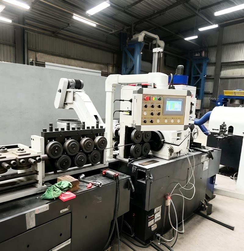
코일에서 바 형태로 가공하는 박피 및 직선화 라인
스테인리스강 와이어 로드는 코일을 풀고 예비 교정 작업을 거친 후, 센터리스 선반을 사용하여 껍질을 벗기고 정확한 길이로 절단합니다. 마지막으로 2롤 교정기를 통해 정밀 교정 작업을 거치면 고정밀 스테인리스강 직선봉이 완성됩니다.
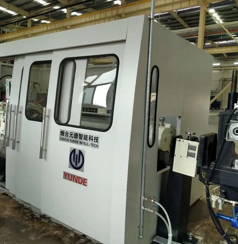
박피기(센터리스 선반)
박피기(무심 선반) 장치는 유사한 해외 제품의 장점을 비교 분석하고 국내 기업의 생산 특성을 고려하여 자체 개발한 제품으로, 간소화되고 최적화된 설계를 특징으로 합니다.
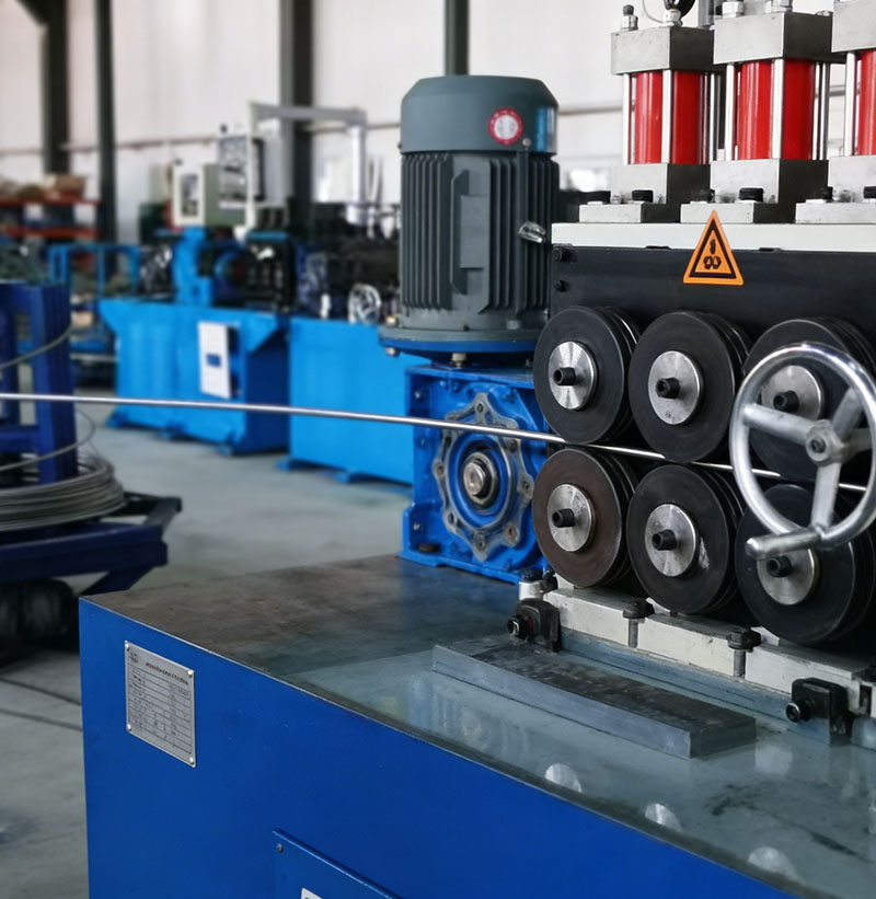
코일 투 코일 생산 라인
코일 생산 라인은 권취 및 교정기, 박피기, 클램핑 장치, 예비 벤딩 장치, 되감기 기계 등 일련의 기계로 구성됩니다. 이러한 기계들을 통해 검은색 코일 봉이 표면 품질이 우수한 밝은 색 코일 봉으로 가공됩니다.
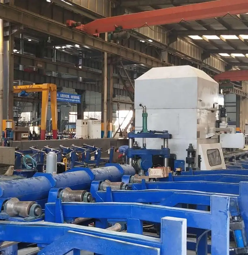
교정기 BS 시리즈
교정기는 금속 프로파일, 봉, 튜브 및 전선을 곧게 펴는 데 사용되는 장치입니다. 교정기는 교정 롤러를 사용하여 재료를 압축함으로써 직선도를 변경합니다. 일반적으로 교정 롤러는 두 줄로 배열되며 롤러의 개수는 다양합니다. 또한 두 개의 롤러(오목한 쌍곡선 모양)의 각도 변화를 이용하여 직경이 다른 재료를 곧게 펴는 2롤러 교정기도 있습니다.
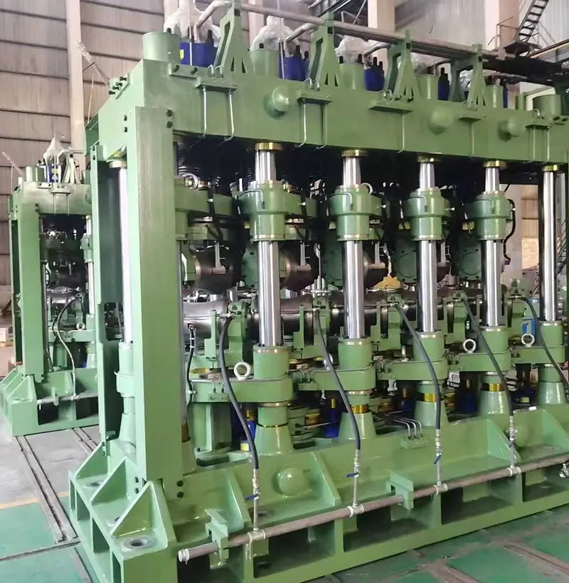
다롤 강관 교정기
강관의 곡률과 타원형 변형을 교정하는 데 사용되는 기계 장치입니다. 고합금강, 내식강, 내열강, 내열강 및 합금강, 철-니켈 합금, 니켈 및 티타늄 합금으로 만들어진 파이프의 종방향 비직선도와 단면 비원형도를 줄이는 데 사용됩니다.
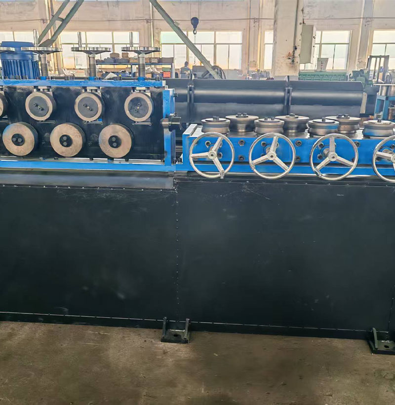
수평 및 수직 교정기
다롤 수평 및 수직 교정기의 핸드휠을 풀어 와이어 코일이 교정 롤러를 통과하도록 합니다. 핸드휠을 실험적으로 결정한 위치로 조이고 공급 장치를 작동시킨 후, 교정 작업을 반복합니다. 그런 다음 수평 교정과 동일한 절차에 따라 와이어 코일을 수직 교정 롤러에 공급합니다. 마지막으로 와이어 코일을 박피기의 공급 장치에 공급합니다.