
ABOUT US
Yantai Yunde Intelligent Technology Co., Ltd. has only 30 years of production experience, has served more than 300 domestic and foreign customers, and has produced more than 2,000 machines.
GET A FREE QUOTE
-
Home

-
Blog
-
Industry Blogs
- How to Select Cutting Tools for Steel Bar Peeling Machines?
How to Select Cutting Tools for Steel Bar Peeling Machines?
-
 author
 - 23,September
A cutting insert that lasts well on one steel batch can chip early on the next. For a steel bar peeling machine, the useful choice depends on what reaches the cutting edge: material hardness, uneven stock, removal depth and machine support. Matching the insert to those conditions helps production teams get acceptable bars through a full run, rather than judging a tool by the first bright surface it produces.
The bar condition defines the cutting task
Tool selection becomes clearer when the incoming bar and the required finished bar are described together. Record the steel grade, hardness condition, starting diameter, final diameter and surface defects. A nominal material name alone leaves too much unanswered, especially when batches arrive with different heat treatments or uneven surfaces.
A peeling machine cuts material away from the outside of the bar. Its tools therefore need enough removal allowance to address the intended surface layer without taking the finished diameter below specification. Deep defects require an engineering decision; a different insert cannot make an inadequate allowance sufficient.
Radial cutting depth is half the diameter reduction for a concentric, uniform cut. For example, reducing a bar from 42 mm to 40 mm means removing 1 mm per side. This is a calculation example, not a recommended setting. Ovality and local surface variation can make the actual load less uniform.

The insert must fit the head and the material
Holder compatibility comes first
The existing holder limits which insert shapes, sizes and seating arrangements can be used. On a round bar peeling machine, confirm those details before comparing grades. An insert that resembles the original is not necessarily interchangeable. Include the cartridge arrangement and any separate roughing and finishing positions in the check.
Carbide grade and edge geometry work together
A carbide grade needs a suitable balance of wear resistance and toughness for the application. Ask the tooling supplier to match its grade to the actual steel and cutting conditions. Simply requesting the hardest insert overlooks how the edge behaves under variable loading.
Geometry determines how that edge engages the material and handles the chip. A grade change alone may leave poor chip control unresolved if the chip breaker does not suit the cutting depth. Select the grade, edge preparation and chip breaker as a combination, using the tooling manufacturer’s application guidance.

Cutting depth gives the chip breaker its job
The planned cut should sit within the insert’s intended working range. A geometry intended for heavy removal may be unsuitable for a light finishing cut. Equally, asking a finishing edge to carry excessive stock removal can undermine reliability. These boundaries belong to the specific tooling system, so universal depth limits are unhelpful.
The following checks connect the production condition to a tooling decision. They are questions for selection and trials, not fixed recipes for every steel.
| Production condition | Selection check | Evidence from the trial |
| Uneven incoming stock | Grade toughness and edge preparation | Chipping or repeated edge damage |
| Light finishing allowance | Geometry for the actual cutting depth | Chip control and surface roughness |
| Substantial stock removal | Roughing geometry and machine capacity | Cutting load and stable chip removal |
| Separate roughing and finishing positions | Depth allocation between inserts | Wear on each cutting position |
The machine’s adjustment system also belongs in this decision. Within YUNDE’s bar peeling machine range, the CNC type supports online electric tool adjustment and closed-loop diameter control. Those functions help manage diameter, but they do not replace a suitable cutting edge or establish that any insert will work at any feed.

A controlled trial reveals the useful tool life
A fair comparison keeps the production conditions visible. For a steel peeling machine, compare candidate tools on representative stock and record the settings used. Changing the grade, cutting depth and feed together makes it difficult to tell which change improved the result.
A practical trial record needs only a few consistent observations:
- Record material grade, hardness, bar dimensions and removal allowance.
- Log insert grade, geometry, cutting speed, feed and cutting depth.
- Measure diameter and surface roughness at agreed intervals.
- Note chip shape, edge condition and the reason for each tool change.
The replacement point should reflect acceptable output. Measure how much conforming peeled steel bar each usable edge produces before the agreed limit is reached. Include tool-change interruptions in the comparison. A longer run has little value if its later bars need rework or fail inspection.
Unexpected chipping deserves investigation before another grade is ordered. Check whether incoming stock, holder condition, seating or support changed during the run. Cutting depth and feed influence productivity, but vibration and machine condition can restrict the settings that remain stable.
A tool choice that survives the production run
The strongest selection is a compatible insert system validated on the steel actually being processed. Match material condition to the grade, match removal depth to the geometry, and compare usable output under recorded conditions. Keep the successful combination as a starting setup for that application, then recheck it when the material or allowance changes.
FAQ
Which cutting tool material should be considered first?
Indexable carbide inserts are a common option for steel bar peeling. The useful specification is more detailed than “carbide”: it includes grade, geometry and compatibility with the installed holder. Confirm the combination for the material and cutting conditions.
Can one insert grade cover every steel batch?
Do not assume it can. Different grades, hardness conditions and surface conditions may call for different tooling. Revalidate an existing choice when the incoming material changes, even if the required finished diameter stays the same.
Does a stronger chip breaker always improve results?
No. Chip-breaker geometry must suit the material, feed and cutting depth. A design intended for a heavier cut may not control chips effectively at a lighter allowance. Use the tool’s recommended application range.
How should tool life be compared?
Compare conforming output per usable edge under equivalent conditions. Record why each edge was replaced, along with downtime and rejected material. Elapsed running time alone can conceal differences in feed or quality.
Should cutting speed rise when surface roughness worsens?
Not automatically. First inspect edge wear, chip control, seating and vibration. Any speed change should remain within the tool and machine limits and be checked through a controlled trial, with diameter and surface roughness measured again.
Recent Post

Related Products
Best-selling Products
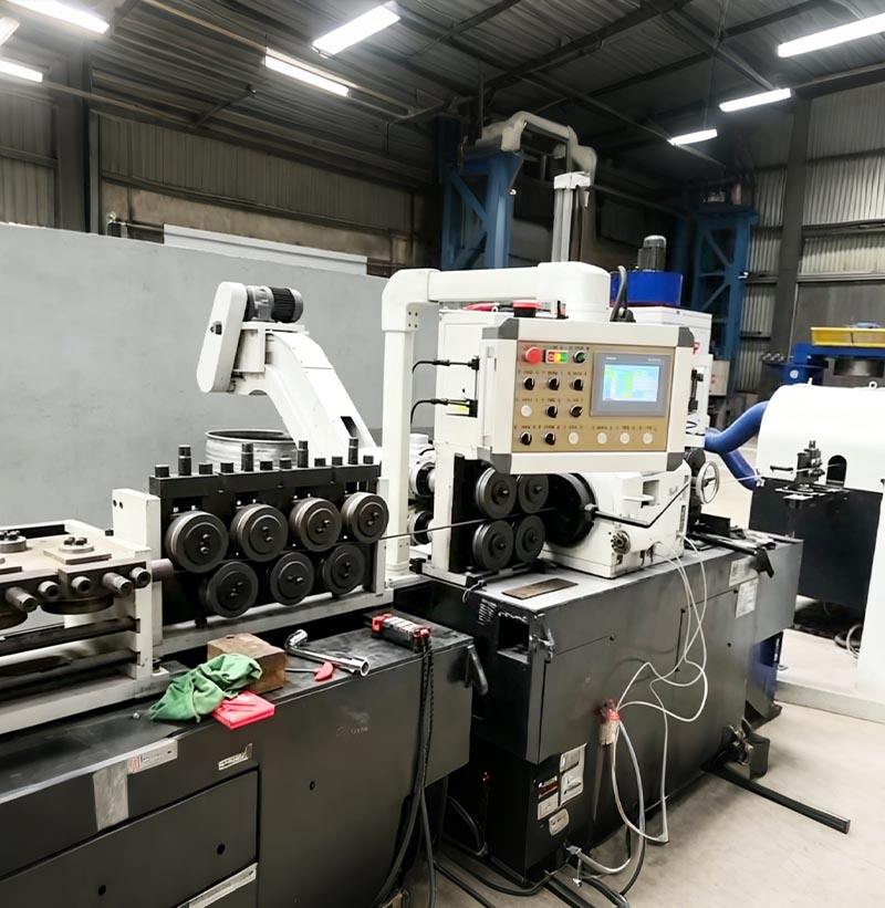
Coil To Bar Peeling&Straightening Line
Stainless steel wire rod is decoiled and pre-straightened, then peeled using a centerless lathe and cut to a precise length. Following a final precision straightening pass through a two-roll straightener, the resulting product is a high-precision stainless steel straight bar.
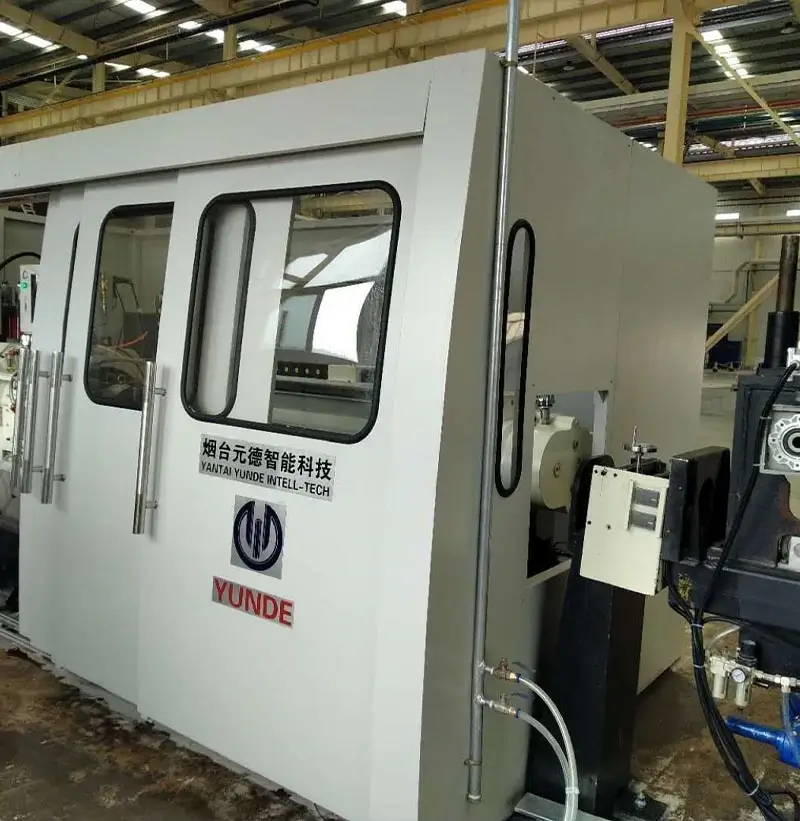
Peeling machine(centerless lathe)
The peeling machine (centerless lathe) unit is a product independently developed after comparing and contrasting the advantages of similar foreign products and combining them with the production characteristics of domestic enterprises, resulting in a simplified and optimized design.
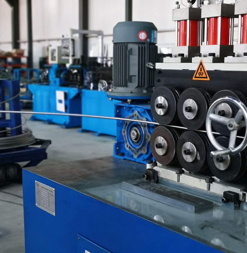
Coil to coil production line
Coil to coil production line is a serial of the machines includes payoff & straightening machine, peeling machine, clamping mechanism, pre-bending device, recoiler machine etc. through above machines, the black coil rod will be processed to bright coil rod with good surface quality
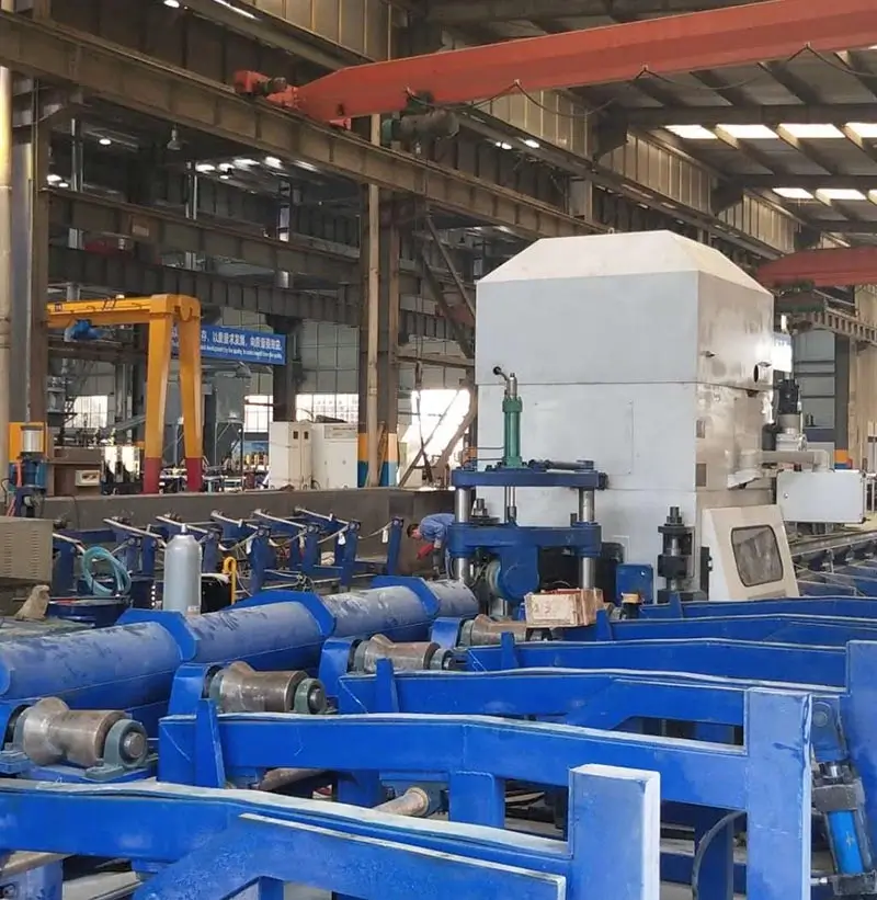
Straightening machine BS Series
A straightening machine is a device used to straighten metal profiles, bars, tubes, and wires. The straightening machine uses straightening rollers to compress the material, altering its straightness. Generally, there are two rows of straightening rollers, with varying numbers of rollers. There are also two-roller straightening machines, which rely on the angle change of two rollers (with a concave, hyperbolic shape) to straighten materials of different diameters.
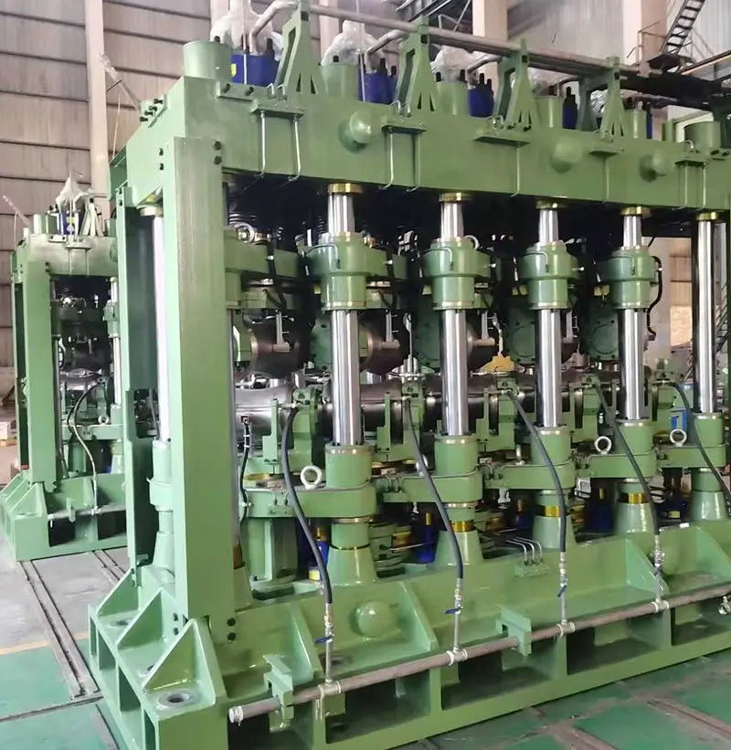
Multi-Roll Steel Pipe Straightening Machine
It is a mechanical device used to straighten the curvature and ovality of steel pipes. It is used to straighten pipes made of high alloy, corrosion-resistant, heat-resistant, heat-resistant steel and alloy, iron-nickel, nickel and titanium alloys , so as to reduce longitudinal non-straightness and cross-sectional non-roundness.
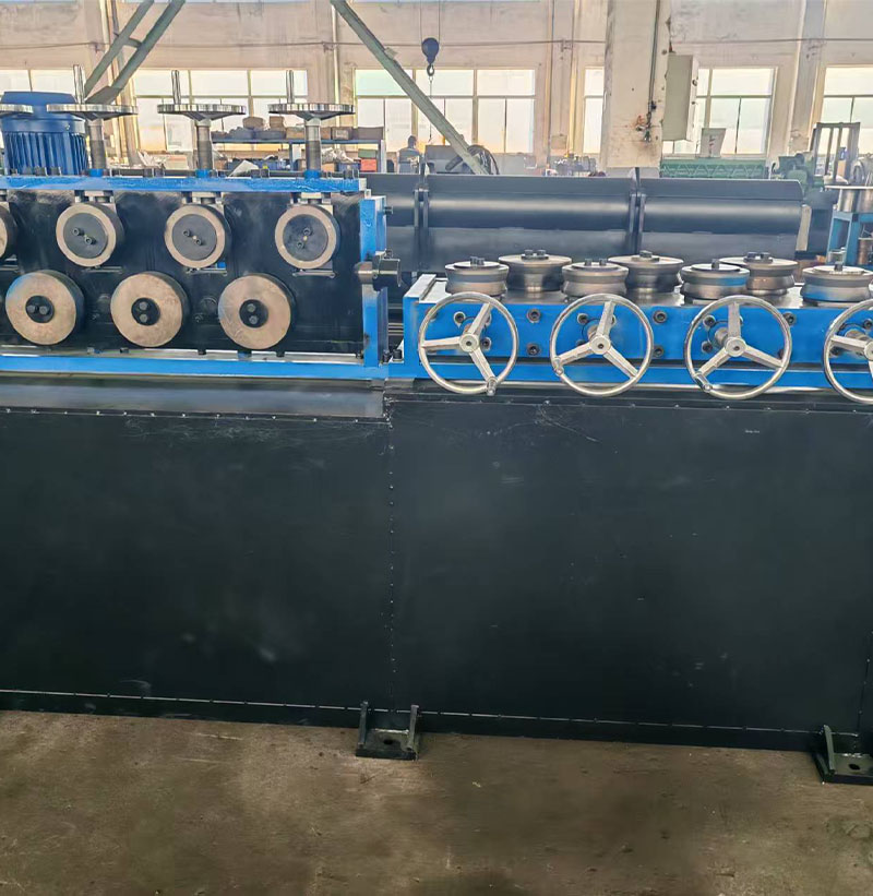
Horizontal and vertical straightening machine
Release the handwheel of the multi-roll horizontal and vertical straightening machine to allow the wire coil to pass through the straightening rollers. Tighten the handwheel to the empirically determined position, start the feeding device, and perform repeated straightening trials. Then feed the wire coil to the vertical straightening rollers, following the same procedure as for horizontal straightening. Finally, feed the wire coil to the peeling machine's feeding device.