
ABOUT US
Yantai Yunde Intelligent Technology Co., Ltd. has only 30 years of production experience, has served more than 300 domestic and foreign customers, and has produced more than 2,000 machines.
GET A FREE QUOTE
-
Home

-
Blog
-
Industry Blogs
- How to Reduce Material Waste in Steel Bar Peeling
How to Reduce Material Waste in Steel Bar Peeling
-
 author
 - 10,September
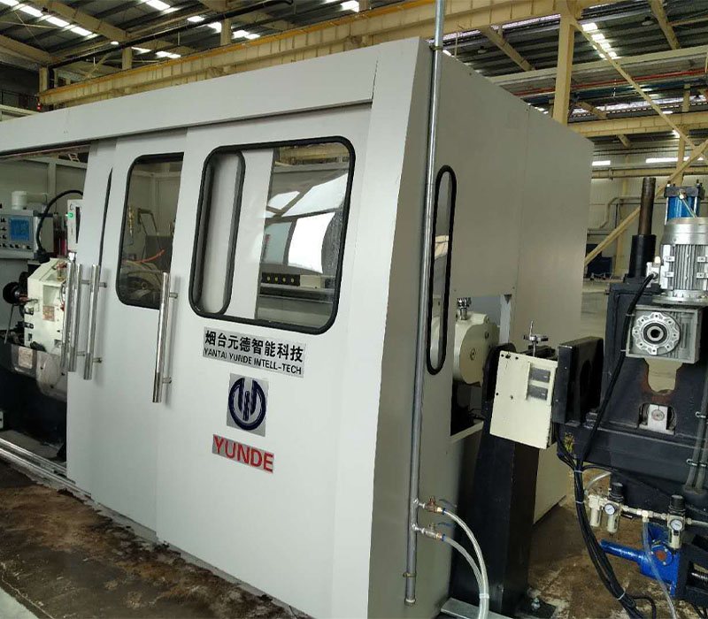
Material loss in bar peeling is often blamed on the cutting head, yet the costly waste usually begins earlier: an uncertain incoming diameter, an allowance set without sample checks, or a tool left in service after the cut has drifted. For a production manager, the useful goal is not the smallest possible cut. It is the smallest controlled removal that still delivers a clean, usable bar.
Where avoidable metal loss begins
Peeling removes a continuous outer layer, so every unnecessary fraction of a millimetre is carried through the entire bar length. That makes allowance discipline more valuable than a late attempt to recover chips. The process should remove scale, decarburized material, and surface defects without turning sound metal into a hidden cost.
Necessary removal versus a safety margin
A bar described as machine turned and peeled is expected to have a consistent finished surface, but consistency does not require a generous allowance on every batch. The planned cut should cover the worst verified condition in the lot, not an assumed defect depth. When raw stock varies widely, separating it into practical condition bands is safer than applying one heavy setting to all bars.
Incoming condition sets the real allowance
A stable waste-reduction plan starts with the bar before it enters the machine. Diameter spread, ovality, straightness, surface scale, defect depth, hardness, and end condition all affect whether the selected cut can remain both safe and economical. A nominal diameter alone cannot describe the material that the cutting tool will actually meet.
*Measure several bars from the lot, including the largest and most visibly affected pieces.
*Record the target finished diameter before setting single-side cutting depth.
*Separate bars with exceptional scale, bends, or local damage for a different setup.
*Check chamfering and end faces so entry and withdrawal stay stable.
*Keep the trial-bar record with the batch instead of relying on a previous setting.
Trial cuts reveal the useful process window
A short trial creates a defensible starting point for a steel bar peeling machine. Measure the trial diameter and surface roughness, then inspect whether the original defects are gone. If a result is acceptable at a lower removal setting, retain that setting and monitor it rather than automatically adding a buffer for the full run.

Machine range defines the practical waste floor
The selected model must cover the actual bar size, length, and required removal range. A machine operating within its intended window gives the operator room to tune the process rather than forcing an aggressive compromise. YUNDE’s PM series below offers fully automatic CNC or semi-automatic configurations, with the same stated diameter tolerance and surface roughness target across the range.
| Model | Diameter mm | Length m | Speed m/min | Cut depth mm/side | Tolerance | Surface roughness μm | Motor kW | Configuration |
| PM25 | Φ6–25 | ≥1.2 | 1–30 | 0.25–1 | ≤IT8 | Ra≤1.6 | 22 | Fully-auto CNC / Semi-auto |
| PM40 | Φ6–40 | ≥1.4 | 1–18 | 0.25–1.5 | ≤IT8 | Ra≤1.6 | 45 | Fully-auto CNC / Semi-auto |
| PM60 | Φ12–65 | ≥2.2 | 1–15 | 0.3–2.5 | ≤IT8 | Ra≤1.6 | 55 | Fully-auto CNC / Semi-auto |
| PM80 | Φ15–80 | ≥2.2 | 1–15 | 0.5–2.5 | ≤IT8 | Ra≤1.6 | 75 | Fully-auto CNC / Semi-auto |
| PM100 | Φ20–100 | ≥2.5 | 1–12 | 1–4 | ≤IT8 | Ra≤1.6 | 90 | Fully-auto CNC / Semi-auto |
| PM130 | Φ35–130 | ≥2.8 | 1–8 | 1–5 | ≤IT8 | Ra≤1.6 | 110 | Fully-auto CNC / Semi-auto |
| PM160 | Φ40–160 | ≥4 | 1–6 | 1–5 | ≤IT8 | Ra≤1.6 | 132 | Fully-auto CNC / Semi-auto |
| PM200 | Φ80–200 | ≥4 | 1–5 | 1–5 | ≤IT8 | Ra≤1.6 | 160 | Fully-auto CNC / Semi-auto |
| PM250 | Φ85–250 | ≥4 | 1–4 | 1–5 | ≤IT8 | Ra≤1.6 | 200 | Fully-auto CNC / Semi-auto |
| PM350 | Φ150–350 | ≥4.5 | 0.2–2 | 1–10 | ≤IT8 | Ra≤1.6 | 200 | Fully-auto CNC / Semi-auto |
A repeatable control loop protects yield
Once a lot is running, a round bar peeling machine should be managed as a measured loop, not a set-and-forget operation. Confirm the first pieces, recheck at planned intervals, and compare diameter, surface roughness, tool condition, and chip form with the trial record. A small correction made early prevents a long run of over-cut bars.
Tool condition appears first in the output
Tool wear can quietly increase cutting load, disturb the finish, and tempt an operator to compensate with deeper removal. That is why checks should follow output signals, not only elapsed time. A bar peeling machine with online electric tool adjustment can make controlled corrections during production, while scheduled inspection keeps adjustment from becoming a substitute for timely tool service.
Tool life and handling complete the waste picture
Tool choice, support, and chip handling influence yield because an unstable cut can damage an otherwise usable bar. Match the cutting tool to the material and planned depth, keep guides and clamping surfaces clean, and remove abnormal pieces before they pass through the full process. Finished handling matters as well: dents after peeling can turn a conforming peeled steel bar into scrap.

Summary
Material waste falls when removal is treated as a verified allowance rather than a precautionary maximum. Inspect incoming stock, prove the setting on a trial bar, use a model that fits the diameter and cut range, and keep checks tied to the output. Those habits preserve sound metal while still delivering the clean surface and dimensional control that downstream machining needs.
If your batches show large variation in diameter or surface condition, talk with our technical team about a trial-based peeling setup for the target finished bar.
FAQ
How does cutting depth affect material waste in bar peeling?
Cutting depth directly determines how much outer material is removed from every bar. Use the lowest verified single-side setting that removes the required defects and still reaches the target finished diameter.
Can one setting be used for every bar in a delivery?
One setting is suitable only when incoming dimensions and surface condition are genuinely consistent. Lots with clear variation should be sampled and, where useful, separated into practical process groups.
Why should a trial bar be measured before full production?
A trial bar confirms that the planned removal achieves the required diameter and surface roughness on the actual stock. It also exposes entry, clamping, or tool issues before they create a long run of loss.
Does faster processing always reduce waste?
Higher speed can improve throughput, but it does not automatically improve yield. The best production rate is the rate that holds a stable cut, controlled surface roughness, and reliable output checks.
Which production records help reduce repeat waste?
Keep the material condition, trial dimensions, cutting depth, speed, tool condition, and inspection results with each batch. Those records make the next setup more precise without copying assumptions from a different lot.
Recent Post

Related Products
Best-selling Products
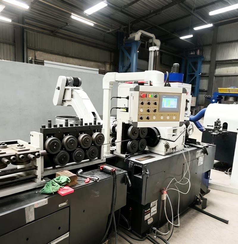
Coil To Bar Peeling&Straightening Line
Stainless steel wire rod is decoiled and pre-straightened, then peeled using a centerless lathe and cut to a precise length. Following a final precision straightening pass through a two-roll straightener, the resulting product is a high-precision stainless steel straight bar.
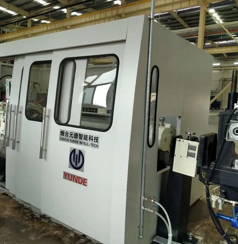
Peeling machine(centerless lathe)
The peeling machine (centerless lathe) unit is a product independently developed after comparing and contrasting the advantages of similar foreign products and combining them with the production characteristics of domestic enterprises, resulting in a simplified and optimized design.
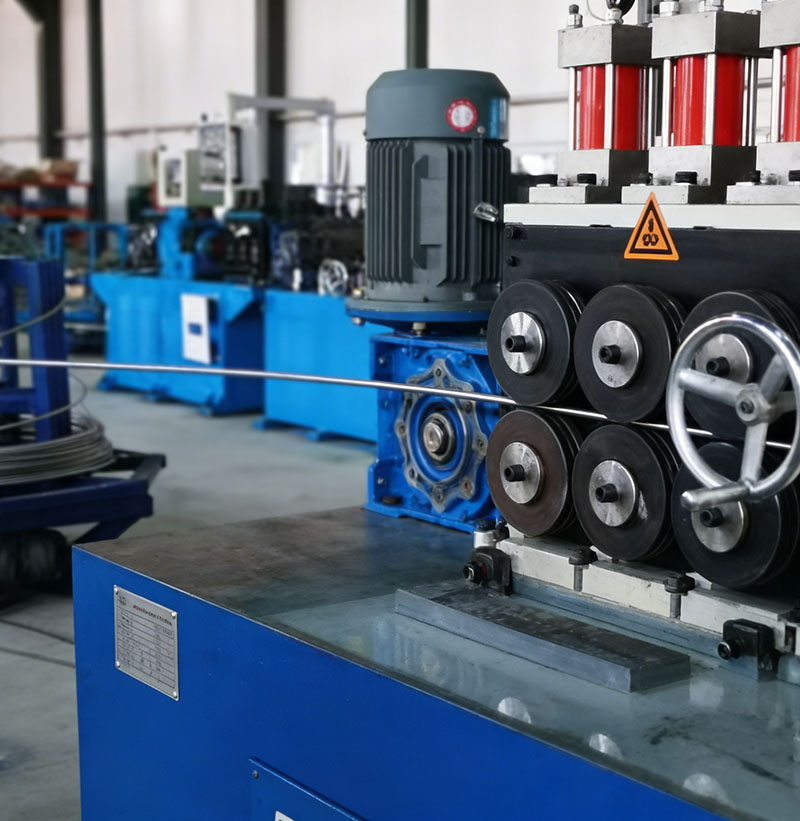
Coil to coil production line
Coil to coil production line is a serial of the machines includes payoff & straightening machine, peeling machine, clamping mechanism, pre-bending device, recoiler machine etc. through above machines, the black coil rod will be processed to bright coil rod with good surface quality
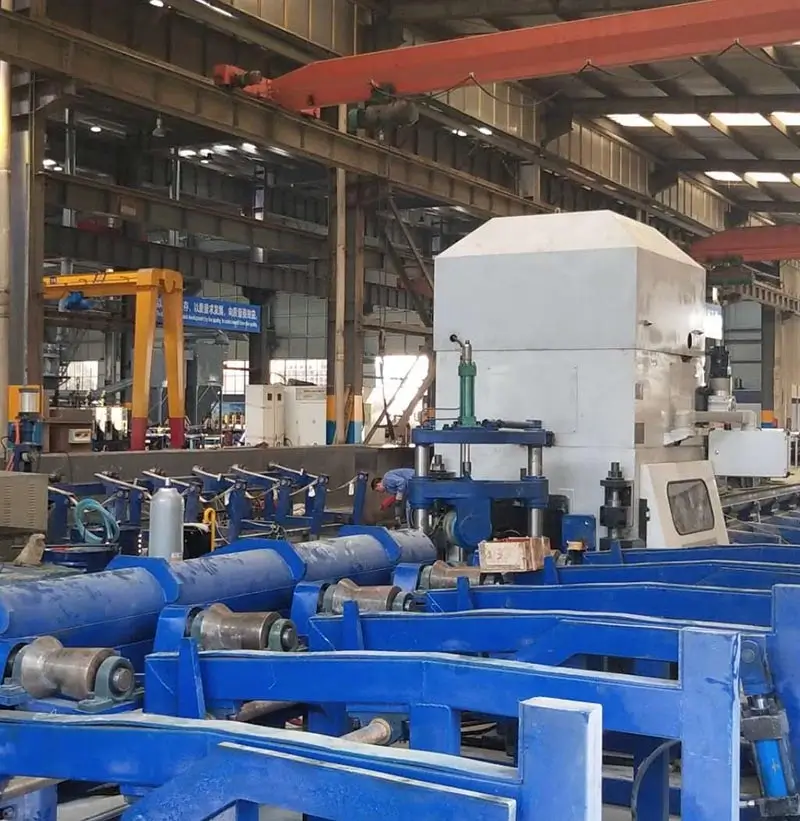
Straightening machine BS Series
A straightening machine is a device used to straighten metal profiles, bars, tubes, and wires. The straightening machine uses straightening rollers to compress the material, altering its straightness. Generally, there are two rows of straightening rollers, with varying numbers of rollers. There are also two-roller straightening machines, which rely on the angle change of two rollers (with a concave, hyperbolic shape) to straighten materials of different diameters.
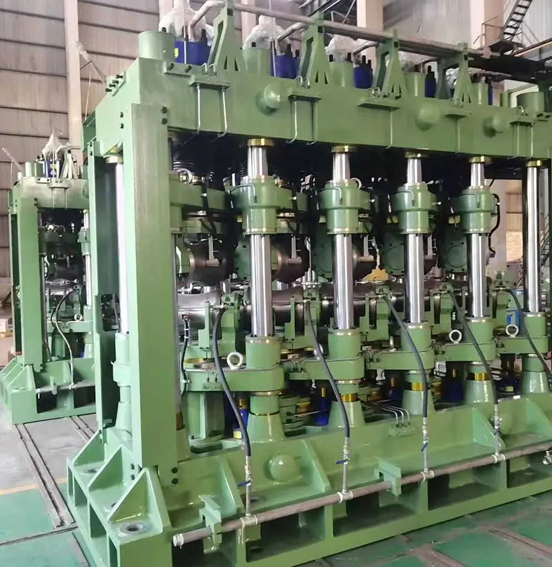
Multi-Roll Steel Pipe Straightening Machine
It is a mechanical device used to straighten the curvature and ovality of steel pipes. It is used to straighten pipes made of high alloy, corrosion-resistant, heat-resistant, heat-resistant steel and alloy, iron-nickel, nickel and titanium alloys , so as to reduce longitudinal non-straightness and cross-sectional non-roundness.
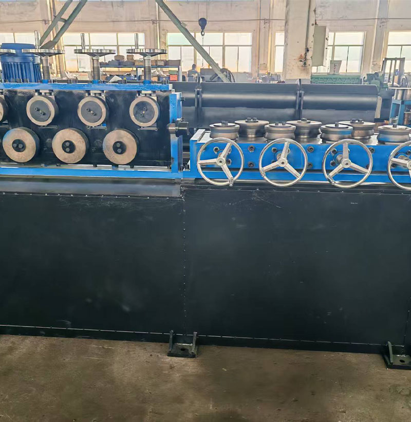
Horizontal and vertical straightening machine
Release the handwheel of the multi-roll horizontal and vertical straightening machine to allow the wire coil to pass through the straightening rollers. Tighten the handwheel to the empirically determined position, start the feeding device, and perform repeated straightening trials. Then feed the wire coil to the vertical straightening rollers, following the same procedure as for horizontal straightening. Finally, feed the wire coil to the peeling machine's feeding device.